PLEASE CHECK IT OUT:
Thursday, 9 June 2011
ASYNCHRONOUS COUNTERS
In the previous section, we saw a circuit using one J-K flip-flop that counted backward in a two-bit binary sequence, from 11 to 10 to 01 to 00. Since it would be desirable to have a circuit that could count forward and not just backward, it would be worthwhile to examine a forward count sequence again and look for more patterns that might indicate how to build such a circuit.
Since we know that binary count sequences follow a pattern of octave (factor of 2) frequency division, and that J-K flip-flop multivibrators set up for the "toggle" mode are capable of performing this type of frequency division, we can envision a circuit made up of several J-K flip-flops, cascaded to produce four bits of output. The main problem facing us is to determine how to connect these flip-flops together so that they toggle at the right times to produce the proper binary sequence. Examine the following binary count sequence, paying attention to patterns preceding the "toggling" of a bit between 0 and 1:
Note that each bit in this four-bit sequence toggles when the bit before it (the bit having a lesser significance, or place-weight), toggles in a particular direction: from 1 to 0. Small arrows indicate those points in the sequence where a bit toggles, the head of the arrow pointing to the previous bit transitioning from a "high" (1) state to a "low" (0) state:
Starting with four J-K flip-flops connected in such a way to always be in the "toggle" mode, we need to determine how to connect the clock inputs in such a way so that each succeeding bit toggles when the bit before it transitions from 1 to 0. The Q outputs of each flip-flop will serve as the respective binary bits of the final, four-bit count:

If we used flip-flops with negative-edge triggering (bubble symbols on the clock inputs), we could simply connect the clock input of each flip-flop to the Q output of the flip-flop before it, so that when the bit before it changes from a 1 to a 0, the "falling edge" of that signal would "clock" the next flip-flop to toggle the next bit:
 This circuit would yield the following output waveforms, when "clocked" by a repetitive source of pulses from an oscillator:
As you can see, the more bits that toggle with a given clock pulse, the more severe the accumulated delay time from LSB to MSB. When a clock pulse occurs at such a transition point (say, on the transition from 0111 to 1000), the output bits will "ripple" in sequence from LSB to MSB, as each succeeding bit toggles and commands the next bit to toggle as well, with a small amount of propagation delay between each bit toggle. If we take a close-up look at this effect during the transition from 0111 to 1000, we can see that there will be false output counts generated in the brief time period that the "ripple" effect takes place:
Instead of cleanly transitioning from a "0111" output to a "1000" output, the counter circuit will very quickly ripple from 0111 to 0110 to 0100 to 0000 to 1000, or from 7 to 6 to 4 to 0 and then to 8. This behavior earns the counter circuit the name of ripple counter, or asynchronous counter.
In many applications, this effect is tolerable, since the ripple happens very, very quickly (the width of the delays has been exaggerated here as an aid to understanding the effects). If all we wanted to do was drive a set of light-emitting diodes (LEDs) with the counter's outputs, for example, this brief ripple would be of no consequence at all. However, if we wished to use this counter to drive the "select" inputs of a multiplexer, index a memory pointer in a microprocessor (computer) circuit, or perform some other task where false outputs could cause spurious errors, it would not be acceptable. There is a way to use this type of counter circuit in applications sensitive to false, ripple-generated outputs, and it involves a principle known as strobing.
Most decoder and multiplexer circuits are equipped with at least one input called the "enable." The output(s) of such a circuit will be active only when the enable input is made active. We can use this enable input to strobe the circuit receiving the ripple counter's output so that it is disabled (and thus not responding to the counter output) during the brief period of time in which the counter outputs might be rippling, and enabled only when sufficient time has passed since the last clock pulse that all rippling will have ceased. In most cases, the strobing signal can be the same clock pulse that drives the counter circuit:
With an active-low Enable input, the receiving circuit will respond to the binary count of the four-bit counter circuit only when the clock signal is "low." As soon as the clock pulse goes "high," the receiving circuit stops responding to the counter circuit's output. Since the counter circuit is positive-edge triggered (as determined by the first flip-flop clock input), all the counting action takes place on the low-to-high transition of the clock signal, meaning that the receiving circuit will become disabled just before any toggling occurs on the counter circuit's four output bits. The receiving circuit will not become enabled until the clock signal returns to a low state, which should be a long enough time after all rippling has ceased to be "safe" to allow the new count to have effect on the receiving circuit. The crucial parameter here is the clock signal's "high" time: it must be at least as long as the maximum expected ripple period of the counter circuit. If not, the clock signal will prematurely enable the receiving circuit, while some rippling is still taking place.
Another disadvantage of the asynchronous, or ripple, counter circuit is limited speed. While all gate circuits are limited in terms of maximum signal frequency, the design of asynchronous counter circuits compounds this problem by making propagation delays additive. Thus, even if strobing is used in the receiving circuit, an asynchronous counter circuit cannot be clocked at any frequency higher than that which allows the greatest possible accumulated propagation delay to elapse well before the next pulse.
The solution to this problem is a counter circuit that avoids ripple altogether. Such a counter circuit would eliminate the need to design a "strobing" feature into whatever digital circuits use the counter output as an input, and would also enjoy a much greater operating speed than its asynchronous equivalent. This design of counter circuit is the subject of the next section.
Since we know that binary count sequences follow a pattern of octave (factor of 2) frequency division, and that J-K flip-flop multivibrators set up for the "toggle" mode are capable of performing this type of frequency division, we can envision a circuit made up of several J-K flip-flops, cascaded to produce four bits of output. The main problem facing us is to determine how to connect these flip-flops together so that they toggle at the right times to produce the proper binary sequence. Examine the following binary count sequence, paying attention to patterns preceding the "toggling" of a bit between 0 and 1:
Note that each bit in this four-bit sequence toggles when the bit before it (the bit having a lesser significance, or place-weight), toggles in a particular direction: from 1 to 0. Small arrows indicate those points in the sequence where a bit toggles, the head of the arrow pointing to the previous bit transitioning from a "high" (1) state to a "low" (0) state:
Starting with four J-K flip-flops connected in such a way to always be in the "toggle" mode, we need to determine how to connect the clock inputs in such a way so that each succeeding bit toggles when the bit before it transitions from 1 to 0. The Q outputs of each flip-flop will serve as the respective binary bits of the final, four-bit count:
If we used flip-flops with negative-edge triggering (bubble symbols on the clock inputs), we could simply connect the clock input of each flip-flop to the Q output of the flip-flop before it, so that when the bit before it changes from a 1 to a 0, the "falling edge" of that signal would "clock" the next flip-flop to toggle the next bit:
The first flip-flop (the one with the Q0 output), has a positive-edge triggered clock input, so it toggles with each rising edge of the clock signal. Notice how the clock signal in this example has a duty cycle less than 50%. I've shown the signal in this manner for the purpose of demonstrating how the clock signal need not be symmetrical to obtain reliable, "clean" output bits in our four-bit binary sequence. In the very first flip-flop circuit shown in this chapter, I used the clock signal itself as one of the output bits. This is a bad practice in counter design, though, because it necessitates the use of a square wave signal with a 50% duty cycle ("high" time = "low" time) in order to obtain a count sequence where each and every step pauses for the same amount of time. Using one J-K flip-flop for each output bit, however, relieves us of the necessity of having a symmetrical clock signal, allowing the use of practically any variety of high/low waveform to increment the count sequence.
As indicated by all the other arrows in the pulse diagram, each succeeding output bit is toggled by the action of the preceding bit transitioning from "high" (1) to "low" (0). This is the pattern necessary to generate an "up" count sequence.
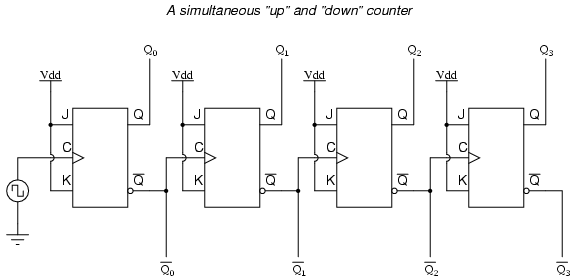
A less obvious solution for generating an "up" sequence using positive-edge triggered flip-flops is to "clock" each flip-flop using the Q' output of the preceding flip-flop rather than the Q output. Since the Q' output will always be the exact opposite state of the Q output on a J-K flip-flop (no invalid states with this type of flip-flop), a high-to-low transition on the Q output will be accompanied by a low-to-high transition on the Q' output. In other words, each time the Q output of a flip-flop transitions from 1 to 0, the Q' output of the same flip-flop will transition from 0 to 1, providing the positive-going clock pulse we would need to toggle a positive-edge triggered flip-flop at the right moment:

Unfortunately, all of the counter circuits shown thusfar share a common problem: the ripple effect. This effect is seen in certain types of binary adder and data conversion circuits, and is due to accumulative propagation delays between cascaded gates. When the Q output of a flip-flop transitions from 1 to 0, it commands the next flip-flop to toggle. If the next flip-flop toggle is a transition from 1 to 0, it will command the flip-flop after it to toggle as well, and so on. However, since there is always some small amount of propagation delay between the command to toggle (the clock pulse) and the actual toggle response (Q and Q' outputs changing states), any subsequent flip-flops to be toggled will toggle some time after the first flip-flop has toggled. Thus, when multiple bits toggle in a binary count sequence, they will not all toggle at exactly the same time:As indicated by all the other arrows in the pulse diagram, each succeeding output bit is toggled by the action of the preceding bit transitioning from "high" (1) to "low" (0). This is the pattern necessary to generate an "up" count sequence.
A less obvious solution for generating an "up" sequence using positive-edge triggered flip-flops is to "clock" each flip-flop using the Q' output of the preceding flip-flop rather than the Q output. Since the Q' output will always be the exact opposite state of the Q output on a J-K flip-flop (no invalid states with this type of flip-flop), a high-to-low transition on the Q output will be accompanied by a low-to-high transition on the Q' output. In other words, each time the Q output of a flip-flop transitions from 1 to 0, the Q' output of the same flip-flop will transition from 0 to 1, providing the positive-going clock pulse we would need to toggle a positive-edge triggered flip-flop at the right moment:
One way we could expand the capabilities of either of these two counter circuits is to regard the Q' outputs as another set of four binary bits. If we examine the pulse diagram for such a circuit, we see that the Q' outputs generate a down-counting sequence, while the Q outputs generate an up-counting sequence:

As you can see, the more bits that toggle with a given clock pulse, the more severe the accumulated delay time from LSB to MSB. When a clock pulse occurs at such a transition point (say, on the transition from 0111 to 1000), the output bits will "ripple" in sequence from LSB to MSB, as each succeeding bit toggles and commands the next bit to toggle as well, with a small amount of propagation delay between each bit toggle. If we take a close-up look at this effect during the transition from 0111 to 1000, we can see that there will be false output counts generated in the brief time period that the "ripple" effect takes place:
Instead of cleanly transitioning from a "0111" output to a "1000" output, the counter circuit will very quickly ripple from 0111 to 0110 to 0100 to 0000 to 1000, or from 7 to 6 to 4 to 0 and then to 8. This behavior earns the counter circuit the name of ripple counter, or asynchronous counter.
In many applications, this effect is tolerable, since the ripple happens very, very quickly (the width of the delays has been exaggerated here as an aid to understanding the effects). If all we wanted to do was drive a set of light-emitting diodes (LEDs) with the counter's outputs, for example, this brief ripple would be of no consequence at all. However, if we wished to use this counter to drive the "select" inputs of a multiplexer, index a memory pointer in a microprocessor (computer) circuit, or perform some other task where false outputs could cause spurious errors, it would not be acceptable. There is a way to use this type of counter circuit in applications sensitive to false, ripple-generated outputs, and it involves a principle known as strobing.
Most decoder and multiplexer circuits are equipped with at least one input called the "enable." The output(s) of such a circuit will be active only when the enable input is made active. We can use this enable input to strobe the circuit receiving the ripple counter's output so that it is disabled (and thus not responding to the counter output) during the brief period of time in which the counter outputs might be rippling, and enabled only when sufficient time has passed since the last clock pulse that all rippling will have ceased. In most cases, the strobing signal can be the same clock pulse that drives the counter circuit:
With an active-low Enable input, the receiving circuit will respond to the binary count of the four-bit counter circuit only when the clock signal is "low." As soon as the clock pulse goes "high," the receiving circuit stops responding to the counter circuit's output. Since the counter circuit is positive-edge triggered (as determined by the first flip-flop clock input), all the counting action takes place on the low-to-high transition of the clock signal, meaning that the receiving circuit will become disabled just before any toggling occurs on the counter circuit's four output bits. The receiving circuit will not become enabled until the clock signal returns to a low state, which should be a long enough time after all rippling has ceased to be "safe" to allow the new count to have effect on the receiving circuit. The crucial parameter here is the clock signal's "high" time: it must be at least as long as the maximum expected ripple period of the counter circuit. If not, the clock signal will prematurely enable the receiving circuit, while some rippling is still taking place.
Another disadvantage of the asynchronous, or ripple, counter circuit is limited speed. While all gate circuits are limited in terms of maximum signal frequency, the design of asynchronous counter circuits compounds this problem by making propagation delays additive. Thus, even if strobing is used in the receiving circuit, an asynchronous counter circuit cannot be clocked at any frequency higher than that which allows the greatest possible accumulated propagation delay to elapse well before the next pulse.
The solution to this problem is a counter circuit that avoids ripple altogether. Such a counter circuit would eliminate the need to design a "strobing" feature into whatever digital circuits use the counter output as an input, and would also enjoy a much greater operating speed than its asynchronous equivalent. This design of counter circuit is the subject of the next section.
LATCHES AND FLIP-FLOPS
Latches and flip-flops
In the same way that gates are the building blocks of combinatorial circuits, latches and flip-flops are the building blocks of sequential circuits.
While gates had to be built directly from transistors, latches can be built from gates, and flip-flops can be built from latches. This fact will make it somewhat easier to understand latches and flip-flops.
Both latches and flip-flops are circuit elements whose output depends not only on the current inputs, but also on previous inputs and outputs. The difference between a latch and a flip-flop is that a latch does not have a clock signal, whereas a flip-flop always does.
Latches
How can we make a circuit out of gates that is not combinatorial? The answer is feed-back, which means that we create loops in the circuit diagrams so that output values depend, indirectly, on themselves. If such feed-back is positive then the circuit tends to have stable states, and if it is negative the circuit will tend to oscillate.
A latch has positive feedback. Here is an example of a simple latch:
This latch is called SR-latch, which stands for set and reset.
It is not practical to use the methods that we have used to describe combinatorial circuits to describe the behavior of the SR-latch. Later, we will show a method for describing flip-flops and clocked sequential circuits. For now, we just rely on our intuition to describe how latches work.
The SR-latch is meant to have at most one of its inputs equal to 1 at any time. When both of its inputs are 0 it has two different stable states possible. Either x is 0, in which case we have the following signal values:
or else x is 1, in which case we have the following signal values:
The actual value depends on the history of input values as we will show next.
Now suppose that s is 1 (and therefore r is 0 since we allow at most one input to be 1 at any time). We get the following signal values:
The 1 on the s input makes sure the output of the upper nor-gate is 0, and the two 0s on the input of the lower nor-gate make sure the x output is 1.
Now suppose the s input goes from 1 to 0, while the r input remains at 0. The second input of the upper nor-gate is 1, so the transition from 1 to 0 of the s input, does not make any difference. The x output remains at 1. In this case, if the s and r inputs are both 0, there is only one possible stable state, the one that gives x the value 1.
Conversely, suppose that r is 1 (and therefore s is 0 since we allow at most one input to be 1 at any time). We get the following signal values:
The 1 on the r input makes sure the x output is 0, and the two 0s on the input of the upper nor-gate make sure the output of the upper nor-gate is 0.
Now suppose the r input goes from 1 to 0, while the s input remains at 0. The second input of the lower nor-gate is 1, so the transition from 1 to 0 of the r input, does not make any difference. The output of the upper nor-gate remains at 1. In this case, if the s and r inputs are both 0, there is only one possible stable state, the one that gives x the value 0.
From the discussion above, we conclude that the SR-latch is able to remember the last state of the inputs, in the sense that it remembers which of the two inputs, s or r, last had the value of 1.
When we need to draw an SR-latch, we use the following symbol:
Flip-flops
Latches are asynchronous, which means that the output changes very soon after the input changes. Most computers today, on the other hand, are synchronous, which means that the outputs of all the sequential circuits change simultaneously to the rhythm of a global clock signal.
A flip-flop is a synchronous version of the latch. To complicate the situation even more, there are several fundamental types of flip-flops. Here, we shall only consider a type called master-slave flip-flop.
In addition to the fundamental types of flip-flops, there are minor variations depending on the number of inputs and how they control the state of the flip-flop. Here, we shall only consider a very simple type of flip-flop called a D-flip-flop. A master-slave D-flip-flop is built from two SR-latches and some gates. Here is the circuit diagram:
The leftmost SR-latch is called the master and the rightmost is called the slave.
Let us first consider what happens when the clock signal is 1. In this case, the two and-gates in front of the input of the master are open, i.e., they let the value of the D-input through to the s input of the master, and the inverse of the D input to the r input of the master. Thus, the value of the D input will go straight trough the master to the x output of the master. But the two and-gates of the slave re closed, i.e., their outputs are always 0, so the slave keeps its old value.
When instead the clock signal is 0, the reverse is true, i.e., the and-gates at the input of the master are closed, whereas the ones at the input of the slave are open. In this case, the flip-flop is completely insensitive to changes in input.
Now, let us consider what happens when the clock goes from 1 to 0. For this to work, we have to assume that the input remains the same during a brief period from right before to right after the clock signal changes. The first thing that happens is that the and-gates at the input of the master turn off, i.e., they become insensitive to further changes in input. The value of the x output of the master is now the value of the D input right before the clock started changing. A brief moment later, the clock signal transition has traversed the inverter and reaches the and-gates of the slave. These gates open, allowing the x output of the master to be propagated to the x value of the slave. The x value of the slave, and therefore that of the entire flip-flop now contains the value of the D input right before the clock started changing. We can say that the clock transition copied the input to the output of the flip-flop. But at no point in time is there a direct path from input to output. The output changes only as a result of clock transitions from 1 to 0.
Finally, let us see what happens when the clock goes from 0 to 1. First, the and-gates of the master open, letting the value of the D input into the master. By the time the D value reaches the master, the clock signal transition reaches the and-gates of the slave, and turns them off before the possibly modified output of the master reaches the slave. Thus, the slave keeps its old value. From the outside, nothing seems to happen, since the output does not change. From now on, however, the master is open to changes in the input.
Here is the symbol we use for D-flip-flops:
The little triangle for the clock input indicates that this input is sensitive only to transitions as opposed to levels as described in the previous paragraph. Sometimes we do not draw the clock input at all when it is understood that it is there. Clock signals are boring since they are all just connected to each other. There is therefore little use to draw them all, and thereby clutter the diagram unnecessarily.
Summary
We have shown how to build a D-flip-flop. It copies its input to its output as a result of a clock signal transition from 1 to 0. The value copied is the value the input has immediately before the clock transition. Most of the clock period, the D-flip-flop is insensitive to changes in the input.
We shall use this key characteristic of the D-flip-flop to build synchronous sequential circuits.
FLIP FLOP
Flip-Flops
extracts from:
http://www.elec.uq.edu.au/~3e211/pracs/prac2/prac2.htm
Dept. of Computer Science and Electrical Engineering
The University of Queensland
St. Lucia Qld 4072 Australia
The memory elements in a sequential circuit are called flip-flops. A flip-flop circuit has two outputs, one for the normal value and one for the complement value of the stored bit. Binary information can enter a flip-flop in a variety of ways and gives rise to different types of flip-flops.
Introduction - Basic Flip-Flop Circuit
A flip-flop circuit can be constructed from two NAND gates or two NOR gates. These flip-flops are shown in Figure 2 and Figure 3. Each flip-flop has two outputs, Q and Q', and two inputs, set and reset. This type of flip-flop is referred to as an SR flip-flop or SR latch. The flip-flop in Figure 2 has two useful states. When Q=1 and Q'=0, it is in the set state (or 1-state). When Q=0 and Q'=1, it is in the clear state (or 0-state). The outputs Q and Q' are complements of each other and are referred to as the normal and complement outputs, respectively. The binary state of the flip-flop is taken to be the value of the normal output.
When a 1 is applied to both the set and reset inputs of the flip-flop in Figure 2, both Q and Q' outputs go to 0. This condition violates the fact that both outputs are complements of each other. In normal operation this condition must be avoided by making sure that 1's are not applied to both inputs simultaneously.
(a) Logic diagram
(b) Truth table
Figure 2. Basic flip-flop circuit with NOR gates
(a) Logic diagram
(b) Truth table
Figure 3. Basic flip-flop circuit with NAND gates
The NAND basic flip-flop circuit in Figure 3(a) operates with inputs normally at 1 unless the state of the flip-flop has to be changed. A 0 applied momentarily to the set input causes Q to go to 1 and Q' to go to 0, putting the flip-flop in the set state. When both inputs go to 0, both outputs go to 1. This condition should be avoided in normal operation.
Back to Contents
Introduction - Clocked SR Flip-Flop
The clocked SR flip-flop shown in Figure 4 consists of a basic NOR flip-flop and two AND gates. The outputs of the two AND gates remain at 0 as long as the clock pulse (or CP) is 0, regardless of the S and R input values. When the clock pulse goes to 1, information from the S and R inputs passes through to the basic flip-flop. With both S=1 and R=1, the occurrence of a clock pulse causes both outputs to momentarily go to 0. When the pulse is removed, the state of the flip-flop is indeterminate, ie., either state may result, depending on whether the set or reset input of the flip-flop remains a 1 longer than the transition to 0 at the end of the pulse.
(a) Logic diagram
(b) Truth table
Figure 4. Clocked SR flip-flop
Back to Contents
Introduction - D Flip-Flop
The D flip-flop shown in Figure 5 is a modification of the clocked SR flip-flop. The D input goes directly into the S input and the complement of the D input goes to the R input. The D input is sampled during the occurrence of a clock pulse. If it is 1, the flip-flop is switched to the set state (unless it was already set). If it is 0, the flip-flop switches to the clear state.
(a) Logic diagram with NAND gates
(b) Graphical symbol
(c) Transition table
Figure 5. Clocked D flip-flop
Back to Contents
Introduction - JK Flip-Flop
A JK flip-flop is a refinement of the SR flip-flop in that the indeterminate state of the SR type is defined in the JK type. Inputs J and K behave like inputs S and R to set and clear the flip-flop (note that in a JK flip-flop, the letter J is for set and the letter K is for clear). When logic 1 inputs are applied to both J and K simultaneously, the flip-flop switches to its complement state, ie., if Q=1, it switches to Q=0 and vice versa.
A clocked JK flip-flop is shown in Figure 6. Output Q is ANDed with K and CP inputs so that the flip-flop is cleared during a clock pulse only if Q was previously 1. Similarly, ouput Q' is ANDed with J and CP inputs so that the flip-flop is set with a clock pulse only if Q' was previously 1.
Note that because of the feedback connection in the JK flip-flop, a CP signal which remains a 1 (while J=K=1) after the outputs have been complemented once will cause repeated and continuous transitions of the outputs. To avoid this, the clock pulses must have a time duration less than the propagation delay through the flip-flop. The restriction on the pulse width can be eliminated with a master-slave or edge-triggered construction. The same reasoning also applies to the T flip-flop presented next.
(a) Logic diagram
(b) Graphical symbol
(c) Transition table
Figure 6. Clocked JK flip-flop
Back to Contents
Introduction - T Flip-Flop
The T flip-flop is a single input version of the JK flip-flop. As shown in Figure 7, the T flip-flop is obtained from the JK type if both inputs are tied together. The output of the T flip-flop "toggles" with each clock pulse.
(a) Logic diagram
(b) Graphical symbol
(c) Transition table
Figure 7. Clocked T flip-flop
Back to Contents
Introduction - Triggering of Flip-flops
The state of a flip-flop is changed by a momentary change in the input signal. This change is called a trigger and the transition it causes is said to trigger the flip-flop. The basic circuits of Figure 2 and Figure 3 require an input trigger defined by a change in signal level. This level must be returned to its initial level before a second trigger is applied. Clocked flip-flops are triggered by pulses.
The feedback path between the combinational circuit and memory elements in Figure 1 can produce instability if the outputs of the memory elements (flip-flops) are changing while the outputs of the combinational circuit that go to the flip-flop inputs are being sampled by the clock pulse. A way to solve the feedback timing problem is to make the flip-flop sensitive to the pulse transition rather than the pulse duration.
The clock pulse goes through two signal transitions: from 0 to 1 and the return from 1 to 0. As shown in Figure 8 the positive transition is defined as the positive edge and the negative transition as the negative edge.
Figure 8. Definition of clock pulse transition
The clocked flip-flops already introduced are triggered during the positive edge of the pulse, and the state transition starts as soon as the pulse reaches the logic-1 level. If the other inputs change while the clock is still 1, a new output state may occur. If the flip-flop is made to respond to the positive (or negative) edge transition only, instead of the entire pulse duration, then the multiple-transition problem can be eliminated.
Back to Contents
Introduction - Master-Slave Flip-Flop
A master-slave flip-flop is constructed from two seperate flip-flops. One circuit serves as a master and the other as a slave. The logic diagram of an SR flip-flop is shown in Figure 9. The master flip-flop is enabled on the positive edge of the clock pulse CP and the slave flip-flop is disabled by the inverter. The information at the external R and S inputs is transmitted to the master flip-flop. When the pulse returns to 0, the master flip-flop is disabled and the slave flip-flop is enabled. The slave flip-flop then goes to the same state as the master flip-flop.
Figure 9. Logic diagram of a master-slave flip-flop
The timing relationship is shown in Figure 10 and is assumed that the flip-flop is in the clear state prior to the occurrence of the clock pulse. The output state of the master-slave flip-flop occurs on the negative transition of the clock pulse. Some master-slave flip-flops change output state on the positive transition of the clock pulse by having an additional inverter between the CP terminal and the input of the master.
Figure 10. Timing relationship in a master slave flip-flop
Back to Contents
Introduction - Edge Triggered Flip-Flop
Another type of flip-flop that synchronizes the state changes during a clock pulse transition is the edge-triggered flip-flop. When the clock pulse input exceeds a specific threshold level, the inputs are locked out and the flip-flop is not affected by further changes in the inputs until the clock pulse returns to 0 and another pulse occurs. Some edge-triggered flip-flops cause a transition on the positive edge of the clock pulse (positive-edge-triggered), and others on the negative edge of the pulse (negative-edge-triggered). The logic diagram of a D-type positive-edge-triggered flip-flop is shown in Figure 11.
Figure 11. D-type positive-edge triggered flip-flop
When using different types of flip-flops in the same circuit, one must ensure that all flip-flop outputs make their transitions at the same time, ie., during either the negative edge or the positive edge of the clock pulse.
Back to Contents
Introduction - Direct Inputs
Flip-flops in IC packages sometimes provide special inputs for setting or clearing the flip-flop asynchronously. They are usually called preset and clear. They affect the flip-flop without the need for a clock pulse. These inputs are useful for bringing flip-flops to an intial state before their clocked operation. For example, after power is turned on in a digital system, the states of the flip-flops are indeterminate. Activating the clear input clears all the flip-flops to an initial state of 0. The graphic symbol of a JK flip-flop with an active-low clear is shown in Figure 12.
(a) Graphic Symbol
(b) Transition table
Figure 12. JK flip-flop with direct clear
Back to Contents
Preparation
Prepare the following in your prac book:
Basic Flip-Flop
Draw the logic circuit for an unclocked NOR gate flip-flop.
Enter the expected timing diagram for signals Q and Q' in Figure 13.
Figure 13. NOR gate flip-flop timing diagram
Draw the logic circuit for an unclocked NAND gate flip-flop.
Enter the expected timing diagram for signals Q and Q' in Figure 14.
Figure 14. NAND gate flip-flop timing diagram
Master-Slave Flip-Flop
Draw the logic circuit implemented with gates for the SR master-slave flip-flop in Figure 9. Use NOR gate flip-flops.
Enter the expected timing diagram for the signals Y, Y', Q, and Q' in Figure 15.
Figure 15. SR master-slave flip-flop timing diagram
Edge Triggered Flip-Flop
Draw the logic circuit for the D-type positive-edge triggered flip-flop in Figure 11.
Enter the expected timing diagram for the signals S, R, Q, and Q' in Figure 16.
Figure 16. D-type edge triggered flip-flop timing diagram
Back to Contents
Procedure
Use LogicWorks to simulate the circuits that you have prepared. Use switches from the I/O library for the inputs and probes from the I/O library for the outputs. Place signal names on the circuit so that the signals are visible in the timing window. Create a separate drawing for each circuit.
To be sure that your circuits don't cross the printing page boundaries, check the Show Page Outlines option from the Drawing|Display Options... menu.
Only print out the circuit and waveforms for the SR master-slave flip-flop.
Back to Contents
Equipment
Computer - Room 47-405
Back to Contents
References
Mano, M., "Digital Design", Prentice/Hall, 1984. Chapter 6.
Smith, R., "Circuits, Devices and Systems", Wiley, 1980.
"LogicWorks for Windows 3.0" by Capilano Computing Systems, Ltd., Addison-Wesley, 1995.
74LS Device Data
Back to Contents

CIRCUITS
Symbolic Logic
Boolean algebra derives its name from the mathematician George Boole. Symbolic Logic uses values, variables and operations :
True is represented by the value 1.
False is represented by the value 0.
Variables are represented by letters and can have one of two values, either 0 or 1. Operations are functions of one or more variables.
AND is represented by X.Y
OR is represented by X + Y
NOT is represented by X' . Throughout this tutorial the X' form will be used and sometime !X will be used.
These basic operations can be combined to give expressions.
Example :
X
X.Y
W.X.Y + Z
Precedence
As with any other branch of mathematics, these operators have an order of precedence. NOT operations have the highest precedence, followed by AND operations, followed by OR operations. Brackets can be used as with other forms of algebra. e.g.
X.Y + Z and X.(Y + Z) are not the same function.
Function Definitions
The logic operations given previously are defined as follows :
Define f(X,Y) to be some function of the variables X and Y.
f(X,Y) = X.Y
1 if X = 1 and Y = 1
0 Otherwise
f(X,Y) = X + Y
1 if X = 1 or Y = 1
0 Otherwise
f(X) = X'
1 if X = 0
0 Otherwise
Truth Tables
Truth tables are a means of representing the results of a logic function using a table. They are constructed by defining all possible combinations of the inputs to a function, and then calculating the output for each combination in turn. For the three functions we have just defined, the truth tables are as follows.
AND
X
Y
F(X,Y)
0
0
0
0
1
0
1
0
0
1
1
1
OR
X
Y
F(X,Y)
0
0
0
0
1
1
1
0
1
1
1
1
NOT
X
F(X)
0
1
1
0
Truth tables may contain as many input variables as desired
F(X,Y,Z) = X.Y + Z
X
Y
Z
F(X,Y,Z)
0
0
0
0
0
0
1
1
0
1
0
0
0
1
1
1
1
0
0
0
1
0
1
1
1
1
0
1
1
1
1
1
Boolean Switching Algebras
A Boolean Switching Algebra is one which deals only with two-valued variables. Boole's general theory covers algebras which deal with variables which can hold n values.
Axioms
Consider a set S = { 0. 1}
Consider two binary operations, + and . , and one unary operation, -- , that act on these elements. [S, ., +, --, 0, 1] is called a switching algebra that satisfies the following axioms S
Closure
If X S and Y S then X.Y S
If X S and Y S then X+Y S
Identity
an identity 0 for + such that X + 0 = X
an identity 1 for . such that X . 1 = X
Commutative Laws
X + Y = Y + X
X . Y = Y . X
Distributive Laws
X.(Y + Z ) = X.Y + X.Z
X + Y.Z = (X + Y) . (X + Z)
Complement
X S a complement X'such that
X + X' = 1
X . X' = 0
The complement X' is unique.
Theorems
A number of theorems may be proved for switching algebras
Idempotent Law
X + X = X
X . X = X
DeMorgan's Law
(X + Y)' = X' . Y', These can be proved by the use of truth tables.
Proof of (X + Y)' = X' . Y'
X
Y
X+Y
(X+Y)'
0
0
0
1
0
1
1
0
1
0
1
0
1
1
1
0
X
Y
X'
Y'
X'.Y'
0
0
1
1
1
0
1
1
0
0
1
0
0
1
0
1
1
0
0
0
The two truth tables are identical, and so the two expressions are identical.
(X.Y) = X' + Y', These can be proved by the use of truth tables.
Proof of (X.Y) = X' + Y'
X
Y
X.Y
(X.Y)'
0
0
0
1
0
1
0
1
1
0
0
1
1
1
1
0
X
Y
X'
Y'
X'+Y'
0
0
1
1
1
0
1
1
0
1
1
0
0
1
1
1
1
0
0
0
Note : DeMorgans Laws are applicable for any number of variables.
Boundedness Law
X + 1 = 1
X . 0 = 0
Absorption Law
X + (X . Y) = X
X . (X + Y ) = X
Elimination Law
X + (X' . Y) = X + Y
X.(X' + Y) = X.Y
Unique Complement theorem
If X + Y = 1 and X.Y = 0 then X = Y'
Involution theorem
X'' = X
0' = 1
Associative Properties
X + (Y + Z) = (X + Y) + Z
X . ( Y . Z ) = ( X . Y ) . Z
Duality Principle
In Boolean algebras the duality Principle can be is obtained by interchanging AND and OR operators and replacing 0's by 1's and 1's by 0's. Compare the identities on the left side with the identities on the right.
Example
X.Y+Z' = (X'+Y').Z
Consensus theorem
X.Y + X'.Z + Y.Z = X.Y + X'.Z
or dual form as below
(X + Y).(X' + Z).(Y + Z) = (X + Y).(X' + Z)
Proof of X.Y + X'.Z + Y.Z = X.Y + X'.Z:
X.Y + X'.Z + Y.Z
= X.Y + X'.Z
X.Y + X'.Z + (X+X').Y.Z
= X.Y + X'.Z
X.Y.(1+Z) + X'.Z.(1+Y)
= X.Y + X'.Z
X.Y + X'.Z
= X.Y + X'.Z
(X.Y'+Z).(X+Y).Z = X.Z+Y.Z instead of X.Z+Y'.Z
X.Y'Z+X.Z+Y.Z
(X.Y'+X+Y).Z
(X+Y).Z
X.Z+Y.Z
The term which is left out is called the consensus term.
Given a pair of terms for which a variable appears in one term, and its complement in the other, then the consensus term is formed by ANDing the original terms together, leaving out the selected variable and its complement.
Example :
The consensus of X.Y and X'.Z is Y.Z
The consensus of X.Y.Z and Y'.Z'.W' is (X.Z).(Z.W')
Shannon Expansion Theorem
The Shannon Expansion Theorem is used to expand a Boolean logic function (F) in terms of (or with respect to) a Boolean variable (X), as in the following forms.
F = X . F (X = 1) + X' . F (X = 0)
where F (X = 1) represents the function F evaluated with X set equal to 1; F (X = 0) represents the function F evaluated with X set equal to 0.
Also the following function F can be expanded with respect to X,
F = X' . Y + X . Y . Z' + X' . Y' . Z
= X . (Y . Z') + X' . (Y + Y' . Z)
Thus, the function F can be split into two smaller functions.
F (X = '1') = Y . Z'
This is known as the cofactor of F with respect to X in the previous logic equation. The cofactor of F with respect to X may also be represented as F X (the cofactor of F with respect to X' is F X' ). Using the Shannon Expansion Theorem, a Boolean function may be expanded with respect to any of its variables. For example, if we expand F with respect to Y instead of X,
F = X' . Y + X . Y . Z' + X' . Y' . Z
= Y . (X' + X . Z') + Y' . (X' . Z)
A function may be expanded as many times as the number of variables it contains until the canonical form is reached. The canonical form is a unique representation for any Boolean function that uses only minterms. A minterm is a product term that contains all the variables of F¿such as X . Y' . Z).
Any Boolean function can be implemented using multiplexer blocks by representing it as a series of terms derived using the Shannon Expansion Theorem.
Summary of Laws And Theorms
Identity
Dual
Operations with 0 and 1
X + 0 = X (identity)
X.1 = X
X + 1 = 1 (null element)
X.0 = 0
Idempotency theorem
X + X = X
X.X = X
Complementarity
X + X' = 1
X.X' = 0
Involution theorem
(X')' = X
Cummutative law
X + Y = Y + X
X.Y = Y X
Associative law
(X + Y) + Z = X + (Y + Z) = X + Y + Z
(XY)Z = X(YZ) = XYZ
Distributive law
X(Y + Z) = XY + XZ
X + (YZ) = (X + Y)(X + Z)
DeMorgan's theorem
(X + Y + Z + ...)' = X'Y'Z'... or { f ( X1,X2,...,Xn,0,1,+,. ) } = { f ( X1',X2',...,Xn',1,0,.,+ ) }
(XYZ...)' = X' + Y' + Z' + ...
Simplification theorems
XY + XY' = X (uniting)
(X + Y)(X + Y') = X
X + XY = X (absorption)
X(X + Y) = X
(X + Y')Y = XY (adsorption)
XY' + Y = X + Y
Consensus theorem
XY + X'Z + YZ = XY + X'Z
(X + Y)(X' + Z)(Y + Z) = (X + Y)(X' + Z)
Duality
(X + Y + Z + ...)D = XYZ... or {f(X1,X2,...,Xn,0,1,+,.)}D = f(X1,X2,...,Xn,1,0,.,+)
(XYZ ...)D = X + Y + Z + ...
Shannon Expansion Theorem
f(X1,...,Xk,...Xn)
Xk * f(X1,..., 1 ,...Xn) + Xk' * f(X1,..., 0 ,...Xn)
f(X1,...,Xk,...Xn)
[Xk + f(X1,..., 0 ,...Xn)] * [Xk' + f(X1,..., 1 ,...Xn)]
**FOR MORE INFO VISIT:http://www.asic-world.com/digital/boolean1.html**
Subscribe to:
Posts (Atom)